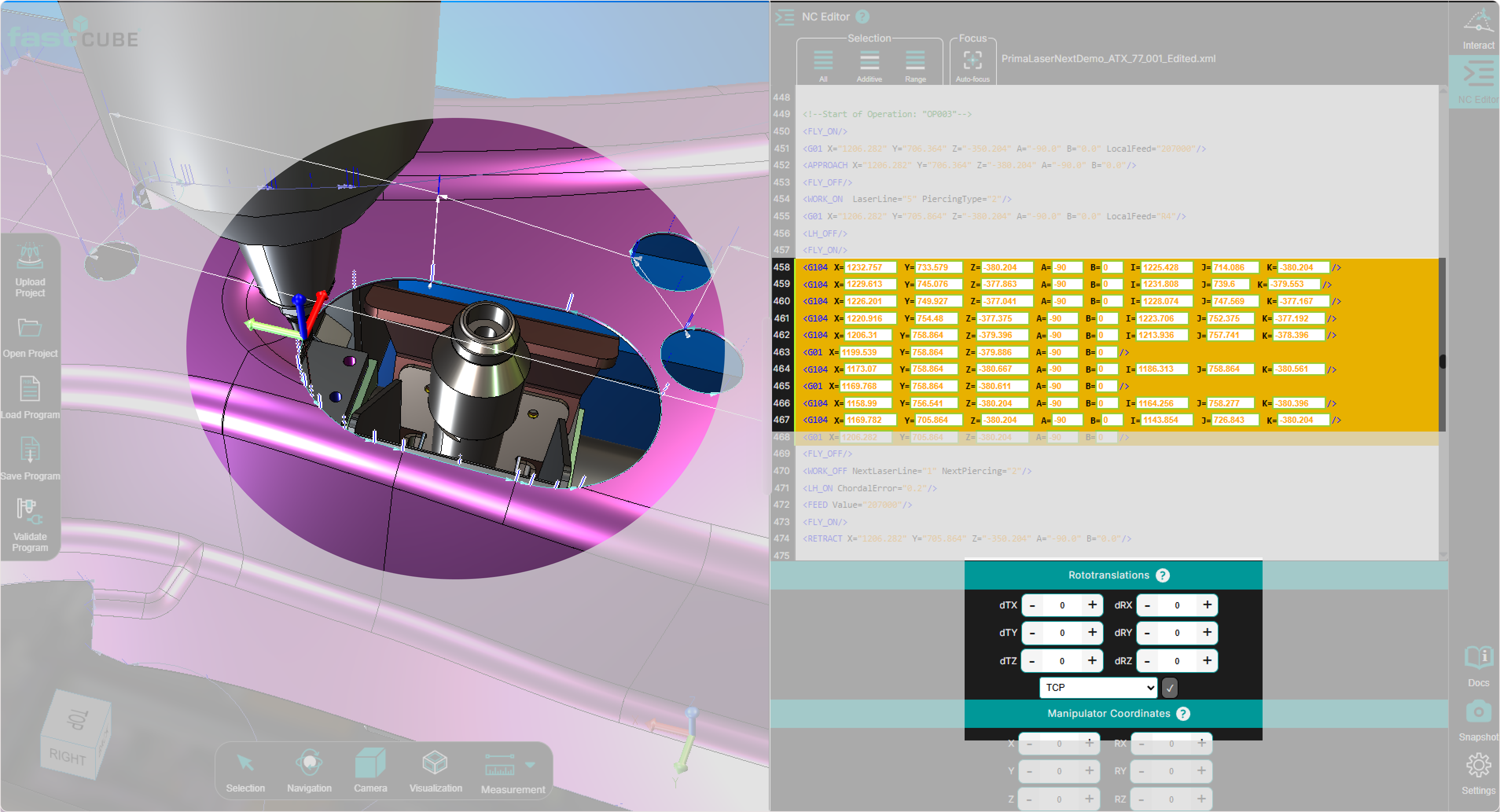
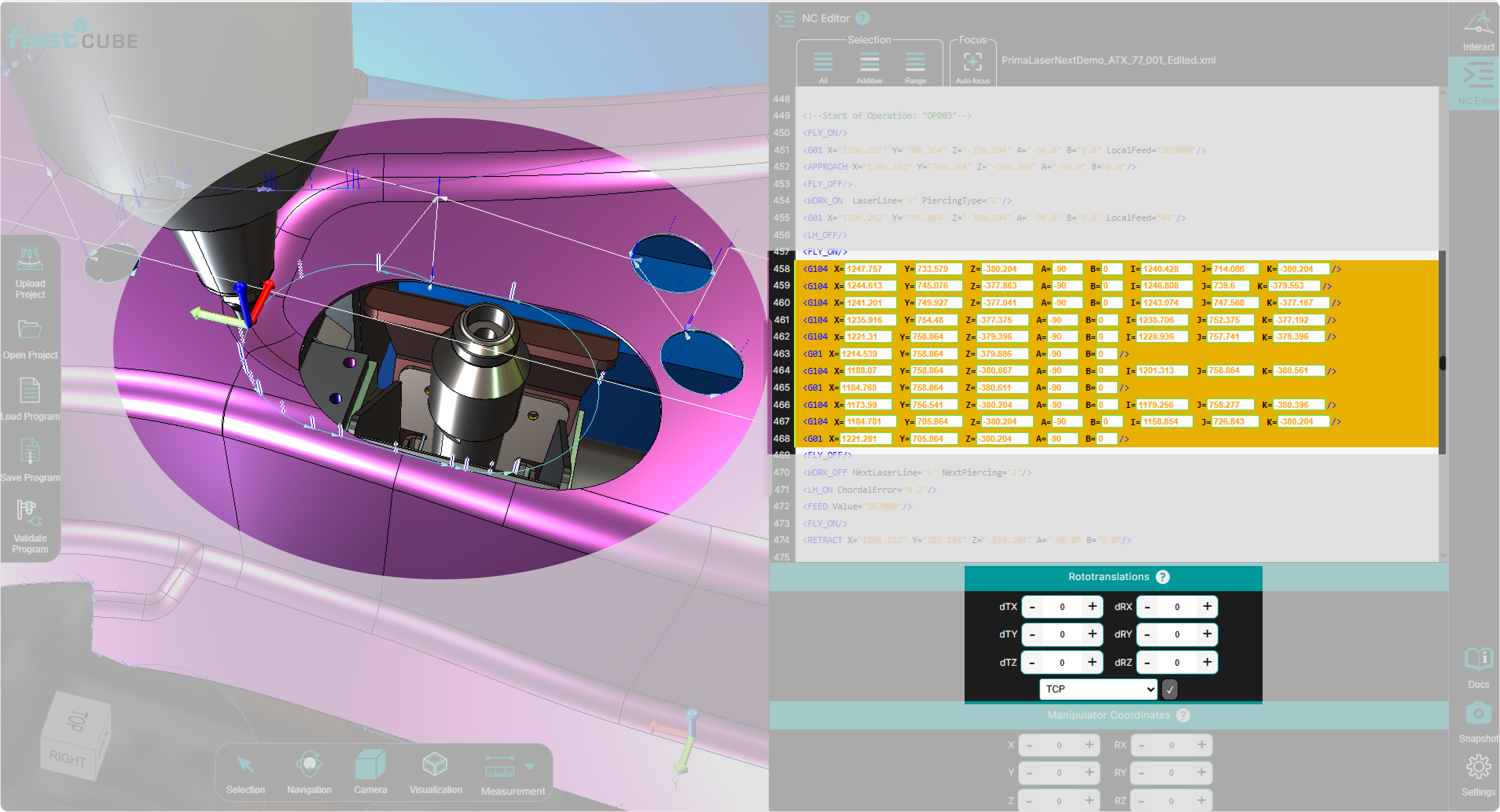
Rototranslation Panel
The Rototranslation Panel is located at the bottom of the NC Editor panel.
It becomes active as soon as one or more points, or an entire Regshape block, are selected in the NC Editor or directly in the 3D Viewer.
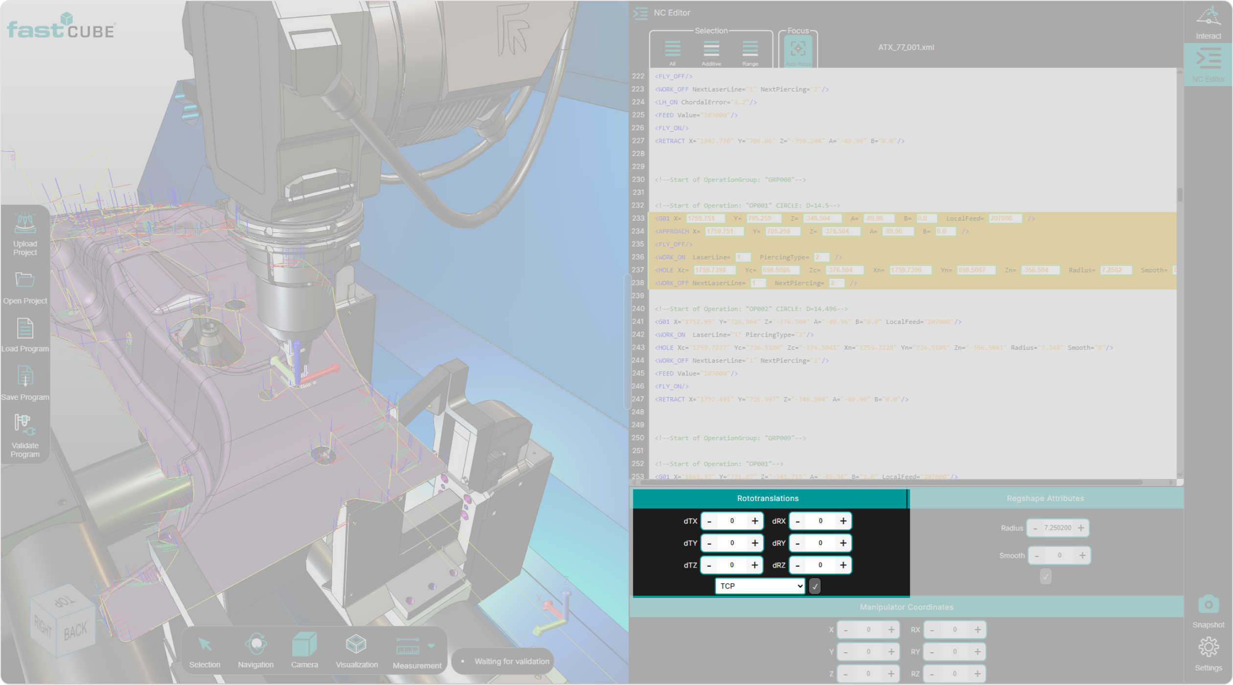
This panel is the primary tool for precise positional adjustments, allowing the operator to apply:
- Translations
- Rotations
- Combined transformations
All transformations are applied relative to a selected reference system (pivot point).
Reference System
Transformations are calculated relative to the active reference system.
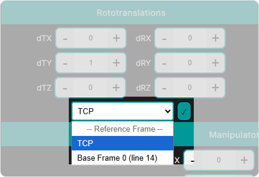
Two reference options are available:
TCP (Tool Center Point)
The transformation uses the tool position as the pivot.
When TCP is active, the Rototranslation Panel works together with the Manipulator and Manipulator Coordinates Panel.
Base Frame (G93 or custom frame)
The transformation is applied relative to the fixed machine frame.
Once Accept is pressed, the transformation is applied and the updated point positions immediately appear in the 3D Viewer.
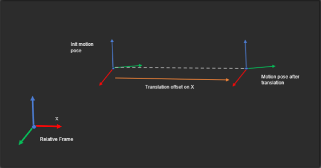
Translation
Translation moves one or more points by applying positional offsets relative to the selected pivot.
Only the point position is updated.
The tool orientation (A, B) remains unchanged.
Step 1 — Select the points
Select the point or group of points you want to translate in the:
- NC Editor
- 3D Viewer
Step 2 — Select the reference system
Choose the pivot reference:
- TCP
- Base Frame
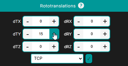
Step 3 — Enter translation offsets
Enter the desired offsets:
- dTx
- dTy
- dTz
These values define how far the points move along each axis.

Step 4 — Apply the transformation
Press Accept to apply the translation.
The updated point positions appear immediately in the 3D Viewer and are written into the NC program.

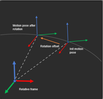
Rotation
Rotation rotates one or more points around the selected pivot point.
Only the point positions are updated.
The tool orientation (A, B) remains unchanged.
Points follow a circular arc defined by:
- the rotation axis
- the pivot reference
Step 1 — Select the points
Select the points or block of points you want to rotate.
Step 2 — Select the pivot reference
Choose:
- TCP
- Base Frame
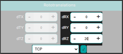
Step 3 — Enter rotation values
Enter the angular offsets:
- dRx
- dRy
- dRz
Values are expressed in degrees.

Step 4 — Apply the rotation
Press Accept to apply the rotation.
The updated toolpath is displayed immediately in the 3D Viewer.

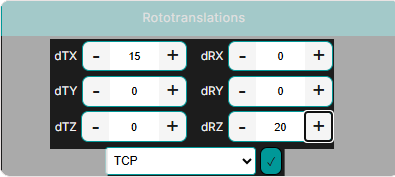
Rototranslation
Rototranslation applies a combined transformation:
- The selected points are rotated around the pivot.
- The points are then translated along the rotated axes.
Tool orientation (A, B) remains unchanged throughout the operation.
Step 1 — Select the points
Select the point or group of points in the NC Editor or 3D Viewer.
Step 2 — Select the reference system
Choose the pivot reference:
- TCP
- Base Frame
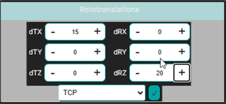
Step 3 — Define the rotation
Enter the rotational offsets:
- dRx
- dRy
- dRz

Step 4 — Define the translation
Enter the translation offsets:
- dTx
- dTy
- dTz
Step 5 — Apply the transformation
Press Accept to apply the combined transformation.

The updated point positions appear immediately in the 3D Viewer and are written into the NC program.
Notes for Operators
- Only the point positions are modified during transformations. The tool orientation (A, B) remains unchanged.
- Always verify the active reference system before applying a transformation. Using TCP or Base Frame can produce significantly different results.
- TCP reference is recommended for fine local adjustments relative to the tool orientation.
- When a Regshape block is selected, the system preserves the internal geometry of the block automatically.
- If TCP reference is active, the Manipulator resets to the first selected point after each transformation.